Hi, just asking, I'm interested in embedded but as an outsider I fail to understand how would I go about making custom board? I googled a lot, but I still fail to grasp how do you make the board? How do you program the chip? How can you test your board? How can you prototype on an arduino, if you'll use different architecture STM vs Atmega, etc...
I've done some arduino projects using VSCode and Platformio and I want to level up my skill level, however I've been struggling to find a resources that goes throught the process of actually making the product from scratch (starts with nothing and ends with a programmed product on custom board). For example, I have this project of mine where I make smart watches using an arduino and e-ink paper display. I would like to read / watch a resource where I learn to design a board that has custom STM32
I am probably about in the same spot that you are. I've been slowly working my way through this course from Andre LaMothe, I think pieces of it might be applicable for you. It's a Udemy course, so it goes on sale for ~$20ish pretty often, I think it's really well done and I've learned a lot so far.
You could start by doing an io board for one of your stm32 board. You start by doing the schematic in kicad eeschema, debug on the breadboard and then you route the actual pcb in kicad pcbnew. There are a lot of tutorial on YouTube on how to use kicad.
After that you can have it fabricated and assembled in China. It's not a necessity but it is really convenient for surface mounted parts and it is surprisingly inexpensive.
Once your comfortable doing io boards, try to replicate one of your stm32 board.
That will give you an idea about the bare minimum circuit one needs to build a functioning board (crystal, power regulator, boot select buttons, and so on)
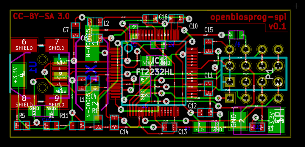
First, make a schematic. This covers which things are electrically connected together so it's easier to see what connections there are. There's always "boilerplate" circuitry, so you'll want to start with an existing schematic. Eg https://stm32-base.org/assets/pdf/boards/original-schematic-...
Then you design the board. You take the schematic, and then actually draw the actual wires (traces) on a board, and tell it which parts go where. The output from this step is a series of Gerber files. They look something like https://info.ewmfg.com/hubfs/Gerber-file-East-West-MFG.png
Finally, you send the board files off to a fab for them to make the board, and optionally solder all the parts on. You used to be able to make it yourself but these days, a pcb house, or manufacturing facility is the way to go.
KiCad is the preferred hobbyist software package these days.
/r/PrintedCircuitBoard/ has some good resources for this process.
> How do you program the chip?
These days, via USB. Circuitry is so cheap these days that the easiest thing to do is have a USB port, and a 'program' button, so when you hold the button down, and power up the device, it boots into a special mode where it can be programmed. There are other techniques but they're mostly harder.
Back in the day, you would have a chip programming device where you would burn the code into a chip, and then have to physically put that chip into your circuit. In order to erase it, you would need to uncover a hole in the top of the chip, and then shine UV light on it.
> How can you test your board?
Depending on the level of debugging you need, a multimeter, a oscilloscope or a digital logic analyzer, in addition to printf debugging and using a debugger, possibly via JTAG.
A multimeter is good enough for simple low/high testing. Like why is this single LED not on, it should be one.
An oscilloscope is useful for graphing simple signals that a multimeter can't catch. If you're turning the LED on and off 50 times a second, it'll be dimmer than if it's just on the whole time (PWM), and an oscope is good for looking at those 50 times.
Finally, a digital logic analyzer. If you're using a bus, like I²C or SPI, and are sending bytes and bytes of data, you can read those off an oscilloscope; low, high, low low is a 4, but that gets old real quick. A digital logic analyzer will interpret the signals on the wire and just tell you the bytes.
Most chips will have a serial port so you can do printf/console.log-grade debugging. You may need additional circuitry to talk to this port, or it may happen over USB.
Finally some microcontrollers support in-circuit emulation (ICE) debugging methods. The two big ones are JTAG and SWE. These let you connect your computer to the microcontroller, and then step through your code, line by line, using a debugger.
> How can you prototype on an arduino, if you'll use different architecture STM vs Atmega, etc...
To be clear, that's not recommended. You're writing in C, not assembly so the code you write is largely portable, so it's just a matter of copying your code to a different configuration, updating the code that interacts with the chip's hardware, and then recompiling.
Updating the code may or may not be trivial though. And personally it's not especially fun. I'd just use the same chip for prototyping as I'd want in my production run. If you have your heart set on using an STM32, just use a dev kits for that to prototype with eg https://www.digikey.com/en/products/detail/stmicroelectronic... instead of an Arudino.
And of course, these days, and on the linked article, you can program in MicroPython instead of C, which is easier.
This was a great answer but the mashup of wildly varying abstraction levels made me chuckle a little. “Debugging? You’ll need printf()… and an oscilloscope.”
chip on it, e-ink display sawthered on and etc, just get me from my prototype to a full on product. Basically, I want to advance my skills to the next level, but I struggle to find how :/ .... you seem to have experience in this kind of stuff, could you please answear some of these questions?
Ps: accidentally posted before I finished the comment and using mobile client without ability to edit comments :d
Ps2: these comments are kinda out of context, but it's something that's bothering me for more than a month now.
In theory you can play with KiCad and draw something up. There's lots of tutorials on KiCad. There's always ESP32 layouts online you can start from too. You can probably figure out how to connect the memory bus to your peripherals correctly but there's always mistakes to be made. That's why it's slightly harder than a minor hobby imho since you really want a full electronics bench including logic analyzer. So it's a big expensive hobby.
If you really want a custom board I'd honestly prototype with a dev kit board like the above and then contract out what you really want to a board design company, showing them your hacked up prototype. Expect $30k for an ESP32 layout that precisely does what you want with no fluff and minimal expense. You then send that off to a PCB maker for the first run and test when it gets back. If all is well you send it off again for a larger more cost effective run.